Why Verified Views Use a 50mm Lens
By Marc Sawan
When preparing Verified Views, one of the first photographic specifications you are likely to encounter is the use of a fixed 50mm lens on a full-frame camera.
To someone unfamiliar with Verified View methodology, this can seem unnecessarily prescriptive. If another lens produces a good photograph, why should 50mm matter?
The answer is consistency. A fixed 50mm lens on a full-frame sensor provides a known and repeatable field of view, limits optical distortion and gives a common reference against which photographs from different viewpoints can be prepared and assessed.
It is the benchmark established by the Landscape Institute's TGN 06/19 for technical photography used in Visualisation Types 1, 3 and 4.
That does not mean a 50mm lens must be used in every situation. Constrained urban viewpoints, tall buildings and wide developments can require a different approach. What matters is understanding why the 50mm benchmark exists, when an alternative is appropriate and how any departure from it is recorded.
1 | Where the 50mm Standard Comes From
TGN 06/19 sets a fixed 50mm focal length lens combined with a full-frame sensor as the benchmark for technical photography.
A full-frame sensor measures approximately 36mm by 24mm, corresponding to the frame size of traditional 35mm film.
In landscape orientation, a 50mm lens on this sensor captures a horizontal field of view of just under 40 degrees and a vertical field of view of approximately 27 degrees.
Orientation | Horizontal field of view | Vertical field of view |
|---|---|---|
Landscape | approximately 39.6 degrees | approximately 27 degrees |
Portrait | approximately 27 degrees | approximately 39.6 degrees |
It is worth distinguishing the Landscape Institute guidance from the London View Management Framework, as the two are often discussed together.
TGN 06/19 deals with the photographic and visualisation methodology, including the camera, lens, presentation and level of verification. The LVMF's AVR Levels 0 to 3 describe something different - how much information about the proposed development is shown in the finished image.
The reason for using a fixed lens is primarily consistency rather than image quality.
A fixed focal length keeps the photographic parameters consistent between viewpoints, makes panorama construction more straightforward and provides a predictable basis for matching the virtual 3D camera to the photograph.
TGN 06/19 therefore states that zoom lenses should not be used for the principal photograph. A zoom image can still be provided as a secondary supporting image, for example to show distant detail that is difficult to read in the 50mm photograph, provided its purpose is clearly explained.
It is also important to understand that the figure of 50mm is nominal.
A lens sold as 50mm will not necessarily produce an exact 39.6 degree horizontal field of view in every circumstance. TGN 06/19 notes that the actual field of view can vary, including with focus distance, and may fall within a range of approximately 37 to 42 degrees.
Where the field of view is being used to match a 3D camera mathematically, the actual value for the particular camera and lens combination should therefore be established rather than simply assuming 39.6 degrees.
2 | When the Site Won't Fit a 39.6 Degree Frame
A 50mm lens works well for many viewpoints, but it is not always possible to fit the required view within a single frame.
This is particularly common in dense urban locations, where the photographer may be standing relatively close to a tall building and cannot simply move further away.
The first option is to turn the camera to portrait orientation. This changes the available vertical field of view from approximately 27 degrees to 39.6 degrees.
Where that is still insufficient, TGN 06/19 recommends considering progressively wider fixed lenses in the following order:
35mm
28mm
24mm
24mm tilt-shift
The normal prime lenses should be explored in both landscape and portrait orientation before moving to a tilt-shift lens.
TGN 06/19 gives the example of a proposal approaching around 18 degrees above the horizontal as a situation where a 50mm frame may no longer be sufficient.
A tilt-shift lens is particularly useful where the difficulty is vertical.
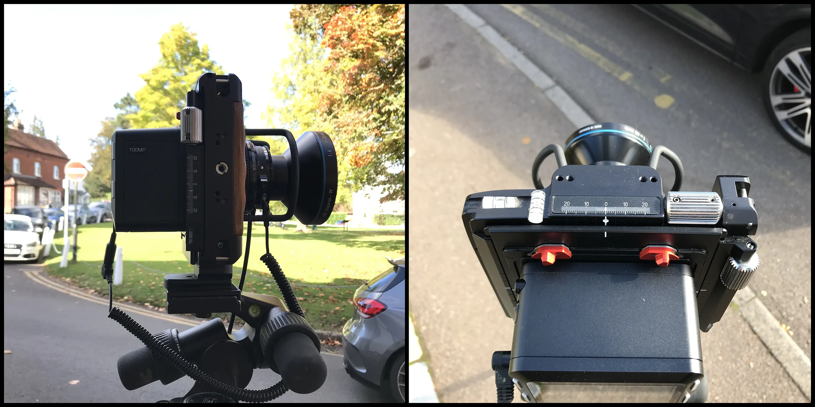
Simply tilting a conventional camera upwards to capture the top of a tall building causes vertical elements within the photograph to converge. A shift lens allows the camera body and sensor to remain level while the lens is shifted vertically, increasing the amount of the scene captured above the normal optical axis.
Because the point of perspective is no longer necessarily at the centre of the image, the finished photograph should clearly identify the optical axis and field of view. The use of the tilt-shift lens and the reason for choosing it should also be recorded in the methodology.
A different solution may be appropriate where the problem is horizontal rather than vertical.
A wide view can be assembled from a series of overlapping 50mm photographs taken from the same camera position. A panoramic head allows the camera to rotate accurately around the lens while controlling the overlap between frames and reducing parallax errors.
With a 50mm lens capturing approximately 39.6 degrees horizontally, photographs taken at roughly 20 degree intervals provide around 50% overlap. The precise overlap can be adjusted to suit the equipment and stitching software being used.
The camera should remain level throughout the panorama. If the camera needs to look significantly upwards or downwards, a conventional stitched panorama may no longer be appropriate and another photographic approach may be required.
3 | Whether 50mm Matches What the Eye Sees
It is often said that a 50mm lens reproduces human vision.
That is useful shorthand, but it is not quite accurate.
TGN 06/19 describes the approximately 40 degree field of view captured by a 50mm lens on a full-frame sensor as being the closest to human eyesight, while also recognising that our peripheral vision is considerably wider.
More importantly, human vision and photography work differently.
We see with two eyes, move them constantly across a scene and experience the world in three dimensions. A photograph records a fixed two-dimensional view from a single camera position.
The 50mm lens should therefore be understood as a useful and consistent photographic reference rather than a literal recreation of human sight.
It also sits between the more obvious optical characteristics associated with wide-angle and telephoto photography.
Wide-angle lenses can introduce greater distortion towards the edges of the image, while longer lenses can produce a stronger visual stacking effect between elements at different distances. A 50mm lens offers a relatively neutral field of view with limited optical distortion.
How the photograph is subsequently presented is just as important.
TGN 06/19 establishes a 50mm photograph with an approximately 39.6 degree horizontal field of view, reproduced at 390mm by 260mm on an A3 sheet, as its 100% reference image.
The mathematically calculated viewing distance for this image is 542mm from the eye. The guidance makes clear that this is simply a mathematical reference point rather than a distance that needs to be measured precisely in practice.
A comfortable viewing distance of approximately 500mm to 550mm - roughly arm's length - is considered more practical.
There is another complication.
Research into large and distant developments, particularly wind farms in open landscapes and seascapes, has found that a 50mm photograph presented at the 100% reference size can make the development appear smaller than it is perceived with two eyes in the field.
For those situations, TGN 06/19 recognises a 150% enlargement, equivalent in presentation terms to an effective focal length of 75mm.
That does not mean every Verified View should be enlarged by 150%.
The guidance also notes that this may overstate scale in more enclosed settings. Research undertaken by the Landscape Institute working group suggested that, for mid-sized and smaller landscapes or townscapes, an enlargement somewhere around halfway between 100% and 150% may provide a closer relationship between the presented photograph and binocular perception.
The appropriate presentation therefore depends on the context and purpose of the view rather than on one enlargement factor being applied universally.
4 | Why the Lens Alone Doesn't Verify Anything
Using the correct lens does not, by itself, make a photograph verified.
The lens controls the field of view and provides a consistent photographic reference. It does not establish exactly where the camera was located in three-dimensional space.
That is a separate part of the verification process.
The importance of camera position depends heavily on the distance between the viewpoint and the subject.
If a proposed building is only a short distance from the camera, a small error in the viewpoint position can noticeably change its relationship with foreground buildings, rooflines or other features.
If the same building is several kilometres away, an equivalent change in camera position will have a much smaller effect on its apparent position.
For this reason, TGN 06/19 takes a proportionate approach to locational accuracy.
For distant subjects, standard GPS accuracy may sometimes be sufficient. In other circumstances, mapping or aerial photography may establish the location to an appropriate level. Where the validity of the image depends on a highly accurate camera position, particularly for close or sensitive views, dedicated survey equipment may be required.
Survey equipment such as GNSS RTK and total stations can establish camera positions and reference points to a high degree of accuracy.
The important point is not that every Verified View must meet one predetermined survey tolerance. The required accuracy should reflect the distance to the proposal, the sensitivity of the view and the purpose of the visualisation.
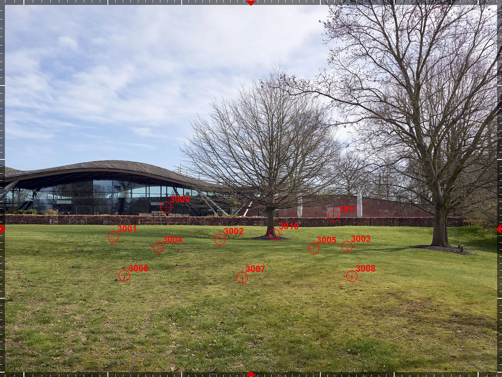
Where survey verification is required, identifiable features within the photographed scene can be recorded and recreated within the 3D environment.
These might include building corners, rooflines, window positions, kerbs or other permanent features.
The virtual camera and proposed development can then be aligned against these known points. This provides a much stronger basis for checking the position of the model than relying on the nominal lens field of view alone.
The AVR Level is a separate issue again. It describes how much information about the proposed development is shown, not how accurately the camera position has been established.
An AVR1 wireline and an AVR3 rendered view can therefore use exactly the same verified camera and model alignment.
5 | What This Means for a Methodology Statement
For anyone commissioning or reviewing Verified Views, specifying a 50mm lens is useful only if the wider photographic and verification process is also documented.
The methodology should record the camera and lens used for each viewpoint, together with the sensor format and field of view.
If another focal length has been used because a 50mm lens could not capture the required view, the reason should be explained.
Where a tilt-shift lens has been used, this should be identified and the point of perspective made clear on the image.
Where a panorama has been constructed, the methodology should explain the photographic approach and equipment used.
The method used to establish the camera location, and the level of locational accuracy appropriate to the project, should also be stated.
For survey-verified views, the methodology should explain how the camera position and relevant control points were recorded and how that information was used to align the 3D model with the photograph.
This documentation is what allows someone reviewing the visualisation to understand how it was produced and, where necessary, check the process.
The 50mm lens is therefore one part of the methodology, not the methodology itself.
Key Takeaways
A fixed 50mm lens on a full-frame sensor is the benchmark. TGN 06/19 uses this combination as the principal reference for technical photography used in Visualisation Types 1, 3 and 4.
The main benefit is consistency. A fixed focal length provides consistent image parameters between viewpoints and a reliable basis for panorama construction and 3D camera matching.
50mm is not mandatory in every situation. Where the required view cannot be captured, wider fixed lenses can be considered, progressing through 35mm, 28mm and 24mm before a 24mm tilt-shift lens where necessary.
A 50mm lens does not literally reproduce human vision. It provides a useful single-frame reference with a relatively natural field of view, but human sight is binocular, dynamic and much wider.
Image presentation affects perceived scale. The 100% reference presentation may be appropriate in some situations, while greater enlargement can be appropriate for distant or expansive subjects.
Lens choice and positional accuracy are separate matters. The lens establishes the field of view, while the camera coordinates and control information establish where the photograph was taken from.
The required survey accuracy should be proportionate. Close and sensitive views generally require greater positional accuracy than subjects several kilometres away.
The methodology should explain any departure from the benchmark. Different lenses, tilt-shift photography, panoramas and survey methods should be clearly recorded where they are used.
Continue Reading
Frequently Asked Questions
Why is a zoom lens not acceptable for the baseline photograph?
TGN 06/19 states that zoom lenses should not be used for the principal photograph. A fixed focal length gives greater consistency between viewpoints and ensures that the basic photographic parameters remain controlled and repeatable. A zoom lens may still be useful as a secondary supporting photograph, particularly where distant detail is difficult to read in the principal 50mm image. Where this is done, the zoom image should be shown alongside the main photograph and its purpose clearly explained.
What happens if the top of a tall building sits above the 50mm frame?
The first option is to consider portrait orientation, which increases the vertical field of view from approximately 27 degrees to 39.6 degrees. If the proposal still cannot be captured, TGN 06/19 recommends considering wider fixed lenses in sequence - 35mm, 28mm and 24mm - before using a 24mm tilt-shift lens where necessary. The normal prime lenses should be explored in both landscape and portrait orientation before moving to the tilt-shift option. Whichever approach is used, the reason for departing from the 50mm benchmark should be recorded in the methodology and, where possible, agreed with the relevant authority.
Can a cropped frame camera be used instead of full frame?
For Visualisation Types 1 and 3, TGN 06/19 allows a cropped-frame camera to be used with an appropriate fixed lens. A 35mm prime lens is recommended, producing a field of view slightly narrower than the full-frame 50mm benchmark. Alternatively, a 28mm fixed lens can be used and the resulting photograph cropped to approximately the same 39.6 degree horizontal field of view. For Type 4 visualisations, the Landscape Institute specifies a full-frame sensor. Cropped sensors vary in size between manufacturers and camera models, introducing additional variables that are less suited to the higher level of control required for a verifiable process.
How much positional accuracy does a viewpoint actually need?
There is no single figure that applies to every viewpoint. TGN 06/19 takes a proportionate approach. The closer the proposal is to the camera, the more important an accurately established camera position becomes. For a distant subject several kilometres away, standard GPS accuracy may be sufficient in some circumstances. For close or sensitive views, where a small movement in the camera position could noticeably change the relationship between the proposal and surrounding features, dedicated survey equipment may be appropriate. The methodology should state the level of positional accuracy used, how it was established and why it is appropriate for the particular view.
About Eye-kon
Every viewpoint brings different constraints, from limited space and tall buildings to wider panoramas, survey requirements and planning-specific presentation standards.
At Eye-kon, we assess these conditions at the outset and adapt the photography, survey and camera-matching approach accordingly. Whether this means working with a 50mm lens, using a wider fixed lens, introducing tilt-shift photography or building a stitched panorama, the method is chosen to suit the view and documented clearly.
The result is a consistent, transparent set of Verified Views that meets the technical requirements of the assessment while representing the proposed design as accurately and faithfully as possible.